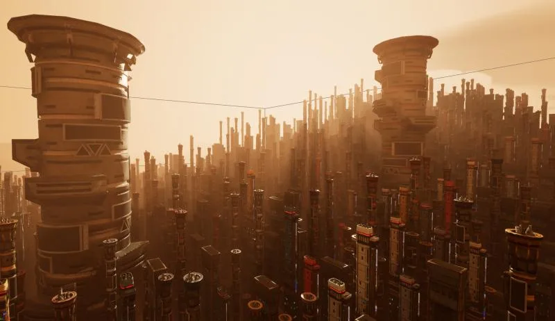
PCG framework makes it easier than ever to generate performant, massive environments and rapidly prototype new levels. This article will go into the basics of writing PCG graphs as well as some more advanced techniques such as the use of attribute partitions to split up generation and spatial noise to create more natural looking environments.
The three nodes you’ll use most commonly in PCG graph are:
- Surface Sample, which samples points along a surface at your desired density.
- Difference, which removes points that overlap with the difference points bounds when using binary inferred mode
- And finally Transform Points, which can be used to randomly move and rotate a set of given points
Layering these nodes together and using Difference nodes to prevent overlapping objects can quickly create complex environments from layers of very simple nodes. For more advanced generation I’ll now talk about the uses of some of the more complex nodes that I don’t see discussed very often.
- Attribute Partition, which splits points into buckets and effectively runs a for-each statement for each group of points with the same target attribute. An example of one use of attribute partition is if you use Transform Points to create a randomly sized box for each point generated by a Surface Sampler (which means that each point in the same box will have the same seed) and you want to generate a separate spline shape for each box. To do this you would need to use an Attribute Partition targeting the Seed attribute, and then the Create Spline node to create the splines. You can now use a Spline Sampler node to create floors, roofs, and walls for your boxes. If you didn’t use an Attribute Partition here you would get one massive jumbled spline instead of the desired multiple splines. Once you’re done with your spline operation you can use a Union node to leave the Attribute Partition and then place meshes or generate more points however you like. Note that because Attribute Partition splits up the point operations generating with it tends to be much slower than generating without it, so you should aim to Union the points back together as soon as you can.
- Spatial Noise, which can use different types of noise such as Voronoi, Fractal Brownian, or Perlin noise to assign weights to the points. By default the weight is assigned to the Density attribute, so you can use a Density Filter node to filter out points according to the spatial noise.
For some extra advanced options I recommend using PCGEx. Note however that PCGEx is still in an early stage of development, and is an unofficial 3rd party plugin. https://github.com/Nebukam/PCGExtendedToolkit. I find it’s pathfinding nodes extremely useful, and will go into detail on some of the nodes I use from it below.
- Pathfinding: Navmesh, which takes an input of Seed points and Goal points and can then use Unreal’s navmesh system to generate paths from seeds to random goals. This is very useful if you want to guarantee navigable paths between exit and entry points in your procedurally generated scene.
- Points to Bounds, which can take in any number of point data sets, such as groups of merged points, and generate a single point with bounds equivalent to all the containing points for each data set.
- Voronoi 2d, which is similar to using the Spatial Node with Voronoi mode but gives you much more control and marks the points with what cluster they belong to.
PCG graph also makes it easy to create new custom nodes. You can do so by inheriting from PCGBlueprintElement and overriding ExecuteWithContext. From here there are several ways of iterating through inputs and modifying them or outputting entirely new outputs. Here are a few resources that go more in-depth on creating custom PCG nodes:
